3rd Assignment's Goal
Each assignment is composed of one or more tasks, which require thought, design, programming or a combination of all. The goal of the 3rd assignment is practice with Hazard and Timing Model Analysis, PTnet transformations, and circuit implementation using the Petrify tool.Task 1 (Timing Model and Hazard Analysis)


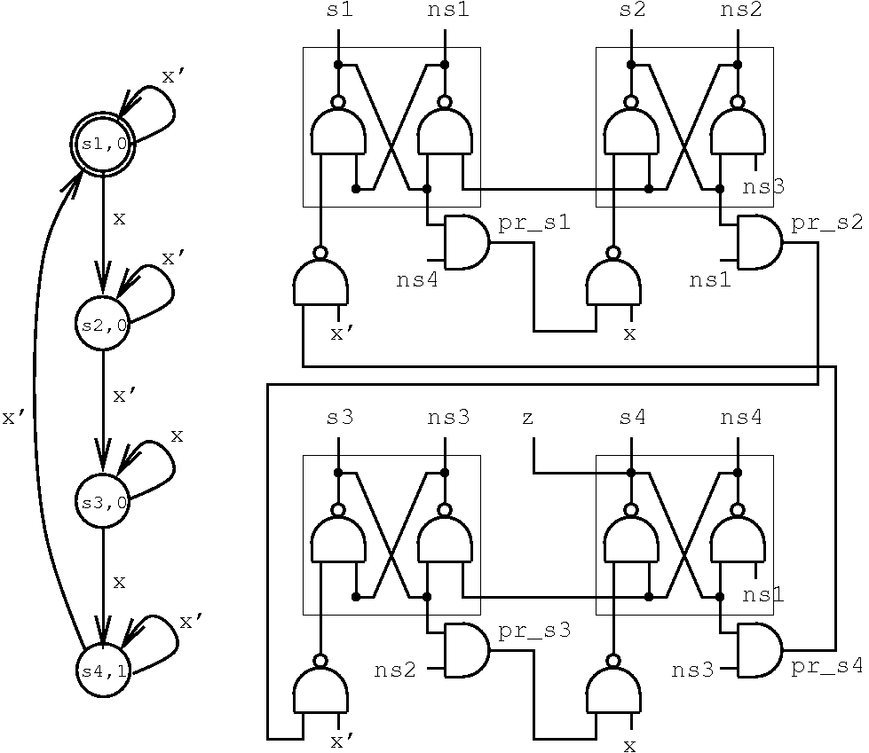
Figure 1 illustrates two control circuits which implement a simple FSM-based counter. Figure 1(a) is a gray-code encoded 2-level implementation, whereas (b) is a corresponding One-Hot version.
Perform Sequential Hazard analysis on circuit 1(a) for initial state Y1Y0 = 00, initial value of input x = 0, and 0&rarr1 transition on x, using both (i) ternary and (ii) 13-level logic. Comment on the differences observed between the two different analysis logics (pros and cons), and the type of manifested Hazards for the given input transition and initial state.
Now, perform the same two analyses to circuit 1(b), but also verifying its timing model. Based on your analysis results, establish whether the Timing Model of circuit 1(b) is SI, Fundamental Mode or Timed (requires specific timing assumptions for correct operation)? Clearly explain why.
Task 2 (PTnet Analysis using SM-Covering)
To compute the minimal Deadlocks use Esparsa's/Kepmper's Algorithm Get_Minimal_Deadlock() repeatedly on uncovered places of the net. Illustrate the resultant SM-Cover, along with a trace of the algorithmic execution for the order of places you specified.
Task 3 (Petrify Tutorial Examples)
Now implement the abc example, of Chapter 4 of the Petrify tutorial. Clearly explain, why the state encoding problem is not solvable, with reference to possible signal paths in the relevant State Graph. Explain clearly (a) what causal environment behaviour which can guarantee that the circuit is SI, and (b) what timing assumption you can introduce to resolve the state encoding conflicts and what of what delay model type this circuit will then be.
Task 4 (STG Circuit Implementation using Petrify)
Firstly, describe the original 4-phase to 2-phase handshake converter PTnet in a Petrify .g file. Note that the aforementioned PTnet includes two Asymmetric Choice (AC) places. Check whether Petrify is able to derive a State Graph or implement this specification. Next, you will have to convert the original PTnet into one without AC places, i.e. into an STG. This may be performed by instantiating the same signal multiple times, and considering the unfolded behaviour of the original PTnet. Describe the derived STG for the 4-phase to 2-phase handshake converter PTnet in a Petrify .g file and (a) derive its State Graph and (b) a Complex Gate implementation, presenting it in schematic form.